
40 CFR 75 requires reporting in standard time year-round and therefore does not allow you to change to daylight saving time. If your computer adjusts for daylight saving time you may have an hour of missing data and an hour of overwritten data.
In accordance with 40 CFR 60 Appendix F, Procedure 1, Section 4.3.1, a calibration drift (CD) failure more than four times the performance specification invalidates data backward to the most recently passed CD. Any QA tests that were performed during the invalidated period are also invalidated. Please note that this failure could invalidate up to 24 hours of data if the unit operates unremittingly. Since not every state permits the use of Part 75 probationary calibrations for units solely under Part 60 regulations, the data could potentially be invalided forward from the failure until a passing CGA and/or RATA is completed.
CiSCO encourages facilities to perform an additional CD immediately following CGA and RATA tests. In the unlikely event that the additional CD fails more than four times the performance specification, the facility will have the opportunity to immediately correct the CD failure and perform the invalidated test(s) again. This is preferable to discovering later that a subsequent CD failure invalidated the QA tests.
The data is also invalid until a passing calibration check has been performed. CeDAR 7 automatically invalidates the data backward to the last passing calibration check using monitor code 74 – Monitor Out of Control 4x PS. The data going forward from the failed calibration check is also invalidated with a monitor code of 11 – Pollutant Analyzer Out of Control for any pollutant (e.g., NOx, CO, SO2, CO2, etc.) calibration fail at four times the performance specification or a monitor code of 12 – Diluent Analyzer Out of Control for an O2 or CO2 calibration fail at four times the performance specification.
PCs in the shelters are considered optional. If you would like to have a ViewNode or RealView set up in the shelter, please contact CiSCO’s software department for options and pricing at (303) 790-1000.
On-Time is the actual time the unit ran, counted from flame on to flame off and is reported in tenths of an hour. Op Hours are the number of clock hours in which the unit operated and are integer values and not portions of an hour. Op Hours are displayed on the Exceedance and Downtime reports; On-Time is displayed on the daily and monthly reports.
The Database Editor does not communicate with the PLCs. Any setting that is written to the PLC must be changed through the Data Monitor, not the Database Editor.
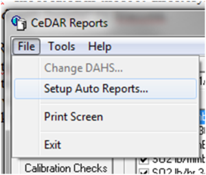
1. In the CeDAR Report Generator, open the File menu and choose “Setup Auto Reports…”.
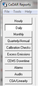
2. On the left-hand side of the screen choose the type of report you would like to have auto reported. In this example we will choose a daily report.
3. Select the ![]() button to setup the auto report.
button to setup the auto report.
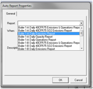
4. In the “Report:” dropdown menu select the report you would like to add.
5. Choose when you would like to print.
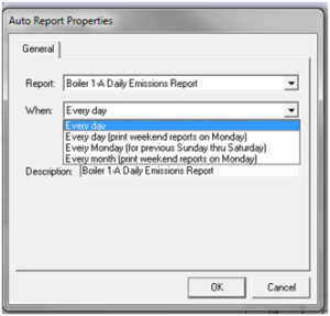
6. Modify the report description as you desire and select OK.
7. At the top of the screen, you can select additional destinations where the auto report will print such as the default printer, named printer, email (PDF), or email (CSV).
![]()
8. If you have any questions or need assistance, feel free to call CiSCO’s Software Support at (303) 790-1000.
Sometimes the startup or shutdown signal from the PLC has a delay or the conditions to determine the turbine status weren’t met at that time. To fix this problem open the Database Editor.
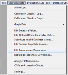
- Select the “Edit/View Data” menu. Select the “Edit Exceedences/Downtimes…” option.
- Choose the date in the calendars displayed at the top of the screen with the exceedance that was supposed to be flagged as startup or shutdown.
- Mark the check box on the right to indicate the parameter is excludable.
- Select the reason box. Click the dropdown menu arrow and choose the appropriate reason from the list.
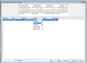
- Choose Save at the bottom of the window and close the Database Editor.
If you have any questions, please feel free to contact CiSCO’s Software Support at (303) 790-1000.
CAL Calibration
CEMS Continuous Emission Monitoring System
CERMS Continuous Emission Rate Monitoring System
CGA Cylinder Gas Audit
CGT Cylinder Gas Test
DAHS Data Acquisition Handling System
DARS Data Acquisition Reporting System
DAS Data Acquisition System
EDR Electronic Data Report
HMI Human Machine Interface (see OIT)
HSL Heated Sample Line
LIN Linearity
OIT Operator Interface Terminal (see HMI)
PB Power Box
PGVP Protocol Gas Verification Program
PLC Programmable Logic Controller
PPM Parts per Million
PS Power Strip
RATA Relative Accuracy Test Audit
SCR Selective Catalytic Reduction
TB Terminal Barrier
TS Terminal Strip
UPS Uninterruptable Power Supply
As of Cedar version 7.24.04 (and all subsequent versions), the tables below show when alarms are generated for cylinder expiration dates. The checks run every day at 10:30 AM.
| Daily Cal Cylinders | |
| Days until expiration | Alarm |
| >60 | None |
| 60 | Warning |
| 4-59 | Warning, Tuesdays Only |
| 2-3 | Warning |
| 0-1 | Serious |
| Expired 1 day | Serious |
| Expired >1 days | None |
| CGA/Linearity Cylinders | |
| Days until expiration | Alarm |
| >60 | None |
| 60 | Warning |
| 31-59 | None |
| 30 | Warning |
| 1-29 | None |
| 0 | Warning |
| Expired | None |
Most CeDAR sites use the hourly average for the measured values instead of calculating the average using the minute data. For example, the hourly average for the NOx at 15% O2, CeDAR would use the hourly average for the O2 percentage and the hourly average for the NOx ppm instead of using the minute averages for the NOx at 15% O2 to calculate the average. All calculations reported in your quarterly 40 CFR 75 EDR follow this methodology.
State and/or local regulatory agencies may require different types of averages for reporting purposes. For example, Pennsylvania Department of Environmental Protection (PADEP) requires the minute values to be used for averages for values at 15% O2, lb/MMBtu, and lb/hr.
- Test results
- 40 CFR 75 megawatts during the test (found in the audit section of the CEDAR Report Generator)
- Protocol Gas Verification Program (PGVP) data for all three levels of NOx and O2 gases including:
-
- Vendor ID
- Cylinder ID
- Gas type (e.g., CO = EPA protocol gas bi-blend consisting of O2, CO, and a balance gas)
- Expiration date
- Gas Level (i.e., low, mid, high)
- Air Emission Testing Board (AETB) information including:
-
- First and last name of the certified RATA team tester
- AETB name (name of the company that performed the RATA)
- AETB phone number
- AETB email address
- Exam date of certified RATA team tester
- Provider name (company that tested and certified the RATA team tester)
- Provider email address
No, only when entering linearity and upscale span gases.
The data is invalid until a linearity is rerun with a non-expired and certified gas cylinder. However, if there is a minimum of 100 psi in the cylinder, you can have it reanalyzed and recertified by the gas vendor.
Have the test team supply their AETB certificates before sending them a PO.
A 40 CFR 75 RATA needs to run at normal or second normal load as shown in the monitoring plan. Make sure you are looking at “40 CFR 75 MW” to determine the load. The High Load is 60‑100% of the range, Mid is 30‑60% and Low is 0‑30%. So, if the low (minimum) MW value is 20 and the high is 120, the High load would be 80-120 MW, Mid 50-80 MW, and the Low 20-50 MW. In contrast, a 40 CFR 60 RATA must be at a MW level that is at least 50% of your normal operating load.
Only if it will allow for the proper load range during the RATA. Please note that in rare cases the permit qualifies duct burner operations as part of normal operations for a 40 CFR 60 RATA.
Use the Resubmit Request Form at http://ecmps.camdsupport.com/help_resubmit_form.shtml to request permission to make changes to your EDR.
Yes, but there is not a specific load requirement.
40 CFR 60, Appendix F does not require the plant to be online, however it is good practice for the stack conditions during a QA test to be similar to those during emission sampling.
40 CFR 60, Appendix A, Method 7E indicates that calibration must be based on the NO gas value. What are the NO/NOX/NO2 requirements for 40 CFR 75 regarding the certified gas values used for calibration, linearity, and the RATA reference analyzer?
Most protocol gas bottles are only certified for the concentration of NO. However, vendors are providing calibration gases that do certify both NO and NOX concentrations. 40 CFR Part 75 Policy Manual Question 9.34 provides options indicating which certified values are appropriate. If the analyzer measures total NOX, you may use either the certified NO concentration or the certified NOX concentration. Otherwise, if the analyzer only measures NO you may only use the certified NO concentration. In addition, an NO2 EPA Protocol Gas must also be used when calibrating a reference analyzer that measures NO and NO2 separately without a converter. If you have any further questions, contact CiSCO’s environmental department at (303) 790-1000.
What is the 4-hour rolling emission limit for a 200 MW CTG having a maximum heat input capacity of 850 MMBtu/hr that includes startup and shut down hours for 40 CFR 60 Subpart KKKK?
Since subpart KKKK is silent on periods of startup, shutdown, and malfunction the general provisions exclude these periods from being considered a violation of the numerical emissions standard. Any 4-hour period that contains either a startup, shutdown, or malfunction would be exempt from being considered a violation of the numerical standard. However, you would still have to report excess emissions for these periods and explain the 4-hour period including SSM and why it is not a violation of the numerical standard.
Because the turbine output is greater than 30 MW, then during startup/shutdown (less than 75% load) the applicable hourly standard would be 96 ppm. If the output was under 30 MW, then it would be 150 ppm. The “north of the arctic circle” rows at the end of Table 1 would apply if any of the listed conditions apply. The actual 4-hour average that they would report excess emissions against is a blended average. For example:
| Hour 1: | Startup (less than 75% of load at some point during the hour) – limit is 96 ppm (could be 150 ppm depending on the output) |
| Hour 2: | Operating at 60% load – limit is 96 ppm |
| Hour 3: | Operating above 75% load for the entire hour – limit is 25 ppm (since maximum heat input is less than 850 MMBtu/hr |
| Hour 4: | Shutdown – limit is 96 ppm for a 4-hour standard. (96 + 96 + 25 + 96)/4 = 78 ppm @15% O2 |
A 3-Load RATA should be performed at least once every five years. In general, a 2-load RATA should be performed annually. If a unit operates within one load at least 85% of the time a single load RATA is acceptable.
Yes, the new RATA should represent an unbiased system.
This error occurs when the bias factor used in the emissions report, generated by breeze75x, is not the same as the bias factor the client tool expects from the last RATA.
- In breeze75x, highlight the data where the bias factor is incorrect (CTRL + Shift) and select the edit button
 .
.
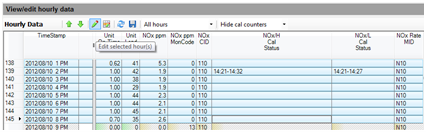
- Change the bias factor to the correct value, choose OK.
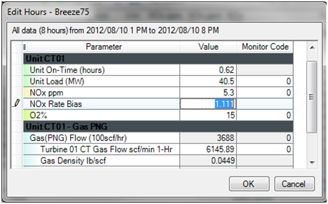
- Finish by selecting the save
 button and refresh the data
  before generating the report to re-import into the Client Tool.
Depending on the age and model of your PLC and panel it may not be possible to enter this information at these locations. However, newer PLCs and panels do support this feature. Since PLCs and panels are unique to sites, there is not an easy way to update existing panels and PLC logic without updating them individually. A change like this would likely require a PLC upgrade since some systems do not have the space or capability to handle alpha numeric fields.
Yes, both CeDAR and breez75x will allow you to enter both capital and lower case letters for the vendor ID. The logic is that at some point, the EPA may add vendor ID’s with lower case letters. breez75x will not convert the lower case letter to a capital letter when you create the EDR. The Client Tool will check vendor ID’s in the EDR against the vendor ID list, so make sure you enter a capital letter if the letter is capitalized on the vendor ID list or the gas certification sheet.
If you have a RealView (which is the Windows-based version of the OIT), CiSCO can enable that feature if it has not been enabled at your site. Contact CiSCO’s software department for more information at (303) 790-1000.
Zero calibrations gases and gases that are Part 60 only do not fall under PGVP and therefore do not get reported or have gas type codes. There are place holders in the settings window in the Data Monitor and the Database Editor for you to track this information.
Quarterly CGA’s do not fall under PGVP because they are a Part 60 requirement, but linearities do require this information because they are a Part 75 requirement. There are place holders in the CGA/Linearity window in the Database Editor for CGA’s in case you would like to track this information. However, you are not required to electronically report this information and there are not any gas type codes for these gases. Newer panels and RealViews also allow you to enter the information for the CGA bottles.
Yes. Enter the same cylinder number in the appropriate place for each unit. However, you cannot use the same cylinder number for different types of gases.
When you recertify a gas, you send it back to the gas company. Once they recertify it, they send it back with a new expiration date, but the cylinder number will stay the same.
Only if the NO2 component is certified. Since NO2 is not very stable, it usually isn’t certified. In that case the code would be NO plus the balance gas. For example, use the code NO,BALN when nitrogen is the balance gas. Check your gas certification sheets or call your gas vendor to see if the NO2 component is certified.
Zero gases do not get reported under PGVP. If you use instrument air to calibrate your O2 span, the gas type code is “AIR” and the cylinder, expiration date, and vendor ID can be left blank.
If the NO2 component is not certified then the gas type code would be NO,CO,BALN.
If this gas is used for Part 60 calibrations, no gas type code is required. Leave this field blank.
Usually, the NO is certified and the NOx is “for reference only”. The certification sheet should tell you whether the NOx is certified or not. If the NOx is certified, you can use that value. If not, you will use the NO value.