
RealView
RealView is a customized Windows-based program used to access the operator interface terminal (OIT) of your analyzers. RealView allows users to view current data, system alarms, and the most recent calibration check, calibration gas audit (CGA) and linearity checks.
The RealView application is convenient and easy to use. You don’t have to navigate through complex menu items to perform simple CEMS tasks. RealView can run on any PC on the same network as the CEMS PLC and can be accessed remotely in the CEMS shelter, the control room, or other office area.
RealView windows allow you to:
- Start a calibration check on a single analyzer or all analyzers at your facility.
- Place the CEMS out of service for maintenance or troubleshooting.
- Put the CEMS back into service after maintenance or troubleshooting.
- Enter cylinder reference gas values for calibration checks, CGA’s and linearity checks.
- Enter Protocol Gas Verification Program (PGVP) cylinder information for 40CFR75 daily calibration checks, such as expiration dates and vendor ID’s.
- Perform a backflush or change the backflush interval.
- Manually control the gas valves in the system.
- Change the daily calibration start times.
- Change other CEMS timing settings, such as cal purge durations.
The Graphic Overview tab gives you an overall picture of the process flow of your CEMS and can be customized for the specifics of each system. The current emission and operational values are displayed on this screen along with a graphic layout of the process flow.
Sample paths change colors when gas is flowing through that specific portion of the system. For example, when a unit is in calibration, the paths change to green indicating that calibration gas is flowing to the probe. Similarly, the paths change to blue when instrument air is in the system. For example, when in backflush, the paths show that instrument air is flowing through the backflush line to the probe. These colors and options can be customized for your facility.
Different areas of the screen turn red when there are alarms. For example, the pressure switches near the top of the window turn red to indicate that there’s an active low cylinder pressure alarm. The probe, sample handling system, and analyzer sections can also be set up to change colors to indicate that there is an alarm in those specific sections of the system.
The Graphic Overview is an optional screen that gives you an overall picture of the process flow of your CEMS and can be customized for the specifics of each system. The current emission and operational values are displayed on this screen along with a graphic layout of the process flow. Please contact CiSCO for pricing to include this screen
RealView – Graphic Overview
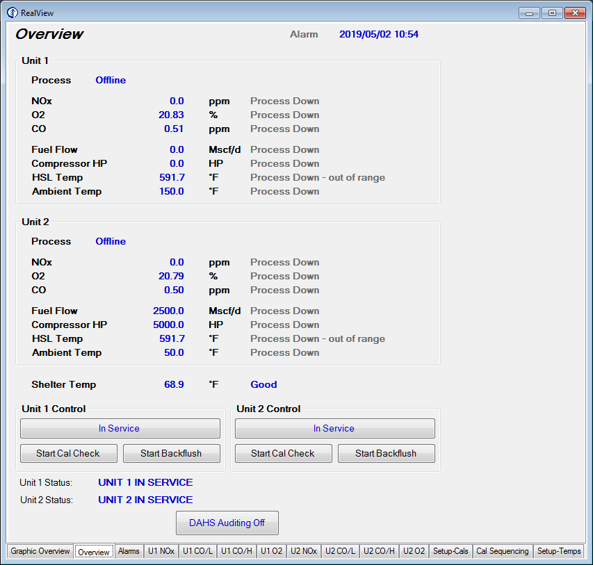
Overview Tab
The Overview tab displays current emission readings for all your analyzers. Operational data such as fuel flow and different temperature readings are also displayed.
This window allows you to place the CEMS in or out of service and start a calibration check or back flush. The unit status is also displayed at the bottom of the window and indicates if the unit is in service or out of service. The status also shows what portion of the calibration sequence the system is currently in, or any valves that are manually open while out of service.
The Overview tab can also include the daily calibration time and/or backflush interval settings.
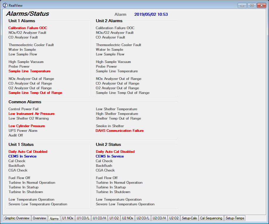
Alarms/Status Tab
The alarms/status tab displays system alarms. Items are shown in red to note that there is a potential problem with the system. The text on these red alarms flashes on and off.
Informational/status indications are shown in blue to note that state as being active, but the system is operating normally.
Inactive items are shown in grey text. All of these colors can be customized on an individual alarm/status basis based on the specific desires of the site.
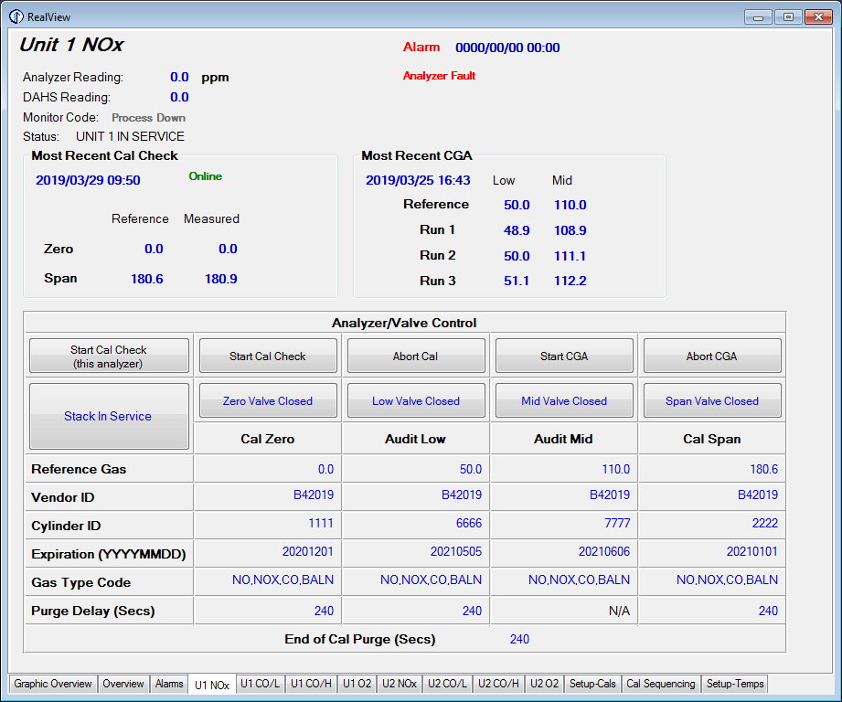
CEMS Analyzer Tab
You will see a tab for each analyzer in RealView. Current emission readings and alarms for that analyzer are displayed in this window. The results of the most recent calibration check and CGA or linearity check are also displayed.
From this window you can:
- Start or abort a calibration check, CGA, or linearity check
- Take the CEMS out of service
- Put the CEMS back into service
- Enter reference gas values for calibration checks, CGA’s, or linearity checks
- Enter PGVP bottle information required by 40CFR75
- Adjust purge delays for the calibration and CGA/Linearity sequences